
Shown
to
the right is an SCR-536 hard at work on the battlefield during World War
Two.
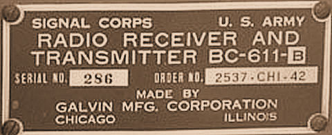
SCR-536 DESCRIPTION
The
SCR-536 consisted of a five valve (four used in transmit and five in
receive mode), low power, battery operated, AM transceiver in a waterproof
case designed
primarily for portability and ease of operation. It featured single
channel crystal control between 3.5 and 6 MHz with a transmit power output
of around 250 mW. Fifty unique frequencies were available through the
changing of crystal and coils sets, although this could not be readily
achieved in the field. Receiver sensitivity was quoted, as being 6 uV while the
SCR-536’s specified range was 1.6 kilometres over open terrain and 4.8
kilometres over salt water. No doubt these distances varied according to
battery condition, position of antenna and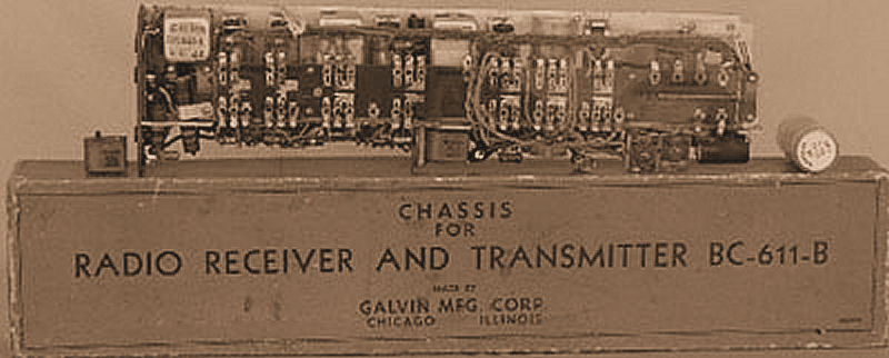 type of vegetation surrounding
the handie-talkie.
type of vegetation surrounding
the handie-talkie.
Power was provided by a 1.5 volt BA-37 dry battery for the filaments and
a 103.5 volt dry battery for the plate supply.
Battery
life was quoted as 19 hours but generally the set was described as battery
‘thirsty’ and, although it was tropicalised, susceptibility to
dampness and mould quite often reduced battery performance.
OPERATION
Extending
the telescopic antenna turned on receiver power,
 while transmit-receive change
over was effected by depressing the SCR-536’s only other operator accessible
control,
the PTT switch. Internal AVC handled volume and the Operator’s
Manual advised reducing the antenna length to reduce receiver overload on very
strong signals!
while transmit-receive change
over was effected by depressing the SCR-536’s only other operator accessible
control,
the PTT switch. Internal AVC handled volume and the Operator’s
Manual advised reducing the antenna length to reduce receiver overload on very
strong signals!
Field
implemented frequency changes were not very practical as two internal crystals
and two coils required replacing, with re-tuning also being necessary. If
required this was usually carried out back at Base prior to field operations.
One can’t help 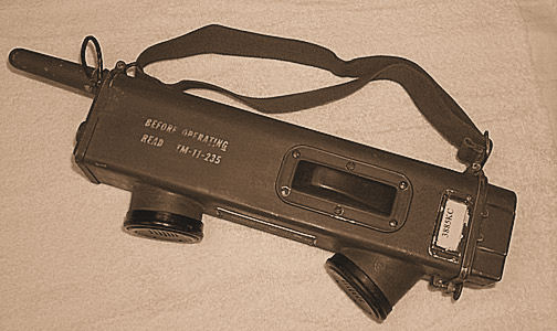 but wonder how, operationally, the problems of a ‘jammed”
frequency channel (jammed either intentionally by the enemy or unintentionally
by other SCR-536 users) were handled on a busy battlefield.
but wonder how, operationally, the problems of a ‘jammed”
frequency channel (jammed either intentionally by the enemy or unintentionally
by other SCR-536 users) were handled on a busy battlefield.
When
the set was not in use the top of the retracted telescopic antenna was
protected by an otherwise retained screw-on cover.
The
version of the SCR-536 shown to the left has a deeper than normal base plate.
This type of base housed two 6.5 mm phono jacks, one for an external
microphone and the other for external headphones.
CIRCUITRY

The
receiver was a single conversion superhet using a 455 KHz IF stage with a RF
amplifier. This configuration opposed the trend of the day where similar
infantry equipment using regenerative receivers was the norm. Not only did the
SCR-536 use a superhetrodyne design but it also had the high receiver
performance (for its time)
 which a RF amplifier stage could provide. Galvin
achieved all this in such a small package by building one of the first true
transceivers where each valve, except the IF amplifier, was used in both
transmit and receive modes. Interestingly this design approach meant that the
PTT switch required a mammoth thirteen poles, nearly all of
which were double
throw.
which a RF amplifier stage could provide. Galvin
achieved all this in such a small package by building one of the first true
transceivers where each valve, except the IF amplifier, was used in both
transmit and receive modes. Interestingly this design approach meant that the
PTT switch required a mammoth thirteen poles, nearly all of
which were double
throw.
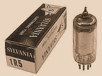
The
valve line up was as follows: 3S4 Rx RF amp, Tx RF Power amp; 1R5 Rx Mixer/Osc,
Tx Crystal Osc; 1T4 Rx IF amp, Tx not used; 1S5 Rx Detector/AVC/AF amp, Tx Mic
preamp; 3S4 Rx AF output stage, Tx Choke modulator. In order to preserve 1.5
volt ‘A’ battery life only one half of the 3S4 filaments were used during
receive and the 1T4 IF amplifier filament was disconnected during transmit. To
change frequency the grid and anode coils of the 3S4 stage were swapped and
realigned. Further, the Tx and Rx crystals were changed, their frequencies
being selected from available fifty different channel pairs.
CONSTRUCTION
The
SCR-536 resembled a bulky telephone handset of lightweight aluminium alloy construction.
The case was of ‘wrap-around’ rectangular design with three internal
parallel compartments. 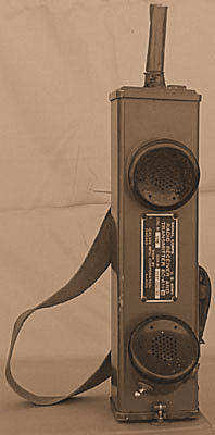 One
accepted the transceiver electronics and integral telescopic antenna. The
second, the radical new ‘layer’ construction BA-38 103.5 volt ‘B’
battery and the third, the BA-37 1.5 volt ‘A’ filament battery. The
transceiver chassis simply slid into its compartment, as did the batteries
into their separately insulated areas. A dynamic microphone and ear-piece were
positioned similar to a telephone handset and a ‘knuckle’ type PTT switch
was positioned for left handed operation. The ‘knuckle’ actuator operated
thirteen sections of the spring-loaded transmit-receive wafer slide switch.
One
accepted the transceiver electronics and integral telescopic antenna. The
second, the radical new ‘layer’ construction BA-38 103.5 volt ‘B’
battery and the third, the BA-37 1.5 volt ‘A’ filament battery. The
transceiver chassis simply slid into its compartment, as did the batteries
into their separately insulated areas. A dynamic microphone and ear-piece were
positioned similar to a telephone handset and a ‘knuckle’ type PTT switch
was positioned for left handed operation. The ‘knuckle’ actuator operated
thirteen sections of the spring-loaded transmit-receive wafer slide switch.
An
innovation of the SCR-536’s construction, which assisted in keeping its
overall size down, was the use of ‘component-cups’. These cups fitted
around each valve base and consisted of two Bakelite shells, or walls, which
contained all the resistors and capacitors directly associated with that
valve. The walls were then filled with a sealing compound and the wiring leads
brought out and soldered into circuit.
Later versions, however, moved away from using these component cups.
Tropicalisation
to moisture and fungi-proof the electronics was performed by spraying the
transceiver chassis with a special varnish.
SCR-536’s ANCESTORS
So
that is the story of the ‘original’ handie-talkie, the one that started
it all. Generally further development of the concept had to wait until the
transistor revolution of the 1960’s. During this period we saw the
emergence of 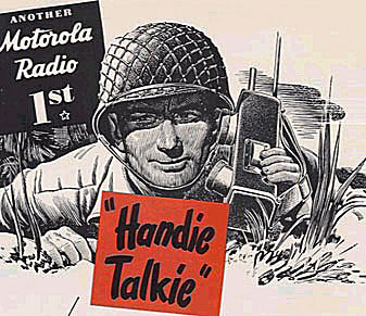 the 27 MHz AM CB ‘walkie-talkie’. Such units came in
transmit power levels of up to 1 watt and had up to four crystal controlled
channels. By today’s standards they were still very large though. Amateurs
didn’t start to see commercially available walkie-talkies until the
seventies, this period signaling the start of the 2 Metre
‘hand-held’s’ ever-increasing popularity.
the 27 MHz AM CB ‘walkie-talkie’. Such units came in
transmit power levels of up to 1 watt and had up to four crystal controlled
channels. By today’s standards they were still very large though. Amateurs
didn’t start to see commercially available walkie-talkies until the
seventies, this period signaling the start of the 2 Metre
‘hand-held’s’ ever-increasing popularity.
Today’s
technology has given us ‘credit card’ size multi-band hand-held’s. And
these days we all take for granted our tiny mobile phones that were
only a dream less than two decades ago.
Surface
mount technology and highly integrated microcontrollers have given today’s
design engineers the freedom to build radios so small that Galvin’s design
team under Don Mitchell would find it hard believe, were they with us today. Furthermore, we
may well ask ‘what will the next 50 years do to the humble handie-talkie?
